
Book Binding Endurance/Strength Testing
Book Binding Endurance/Strength Testing
Introduction
Test-Tech Metrics materials testing provides services to the paper, packaging and plastic film industries. Whilst most testing work is to ISO or other standards, using standard test equipment in an air-conditioned laboratory, Test-Tech Metrics are willing to apply their knowledge and innovation when customers demand something slightly different.
A leading publisher supplied some samples of books, of different construction types and materials, to be evaluated for the endurance and strength of their bindings. After due consideration, four tests were conceived using test equipment adapted for this application. It was intended that the tests would be able to distinguish, by their results, the performance of the different book binding methods.
Initial sample preparation
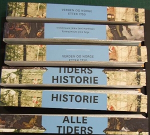
Four tests were to be applied to the samples. Two of the tests (Trouser Tear and MIT Fold) required the complete removal of the pages as shown below.
Two tests, both tensile, were to be made on 25mm sections of complete books which were cut on a guillotine to produce neat cuts:
Testing Procedure
Trouser Tear Test
For this test a whole book was used, but it required reducing in width to 70mm before making two cuts 40mm long, at one end of the book, along the edges of the spine. A “tail” of packaging tape was then attached to the spine at the end which was cut to enable pulling in the tensile testing machine.
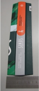
Left: the spine and two narrow cover sections making 70mm width in all.
Right: packaging tape attached to 40mm cut portion of spine which is then clamped in the upper clamp. Lower clamp holds the remaining narrow sections of cover.
The test was based on BS EN ISO 6383-3 (BS 2782-3 Method 360B Determination of tear resistance of plastics film and sheeting by trouser tear method) using an Instron 5565 Tensile Tester equipped with a 100N load cell which confirms to ISO 7500 class 0.5. The gauge length was set to just greater than the book length in each case and the extension rate was 500mm/min. The jaw types used were pneumatic with rubber faces of size 25mm x 50mm.
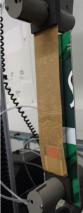
Three test piece replicates were performed. The photographs over show the development of the ‘Sinus 2P-Y’ book as the load was applied. This spine pulled out of the cover uniformly in a rectangular shape.

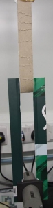
Left: Test piece in progress a short time after the start. Creases visible in the spine correspond to sudden tear after a period of loading.
Right: same test piece approaching the end of the test. Several creases are visible in the torn spine.
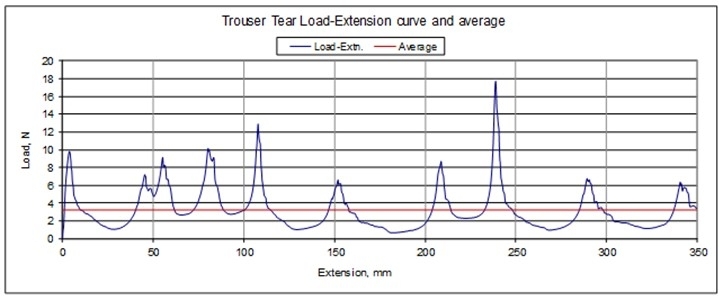
The graph below shows a typical result for the test-piece. The load/tear cycles, that caused the creases in the spine described above, are peaks in the load-extension curve. The load values across the whole extension range were averaged to arrive at a single value for comparison in the data tables. This is shown by the straight line on the graph.
MIT Fold Endurance
This property was measured based on TAPPI test T 511 om-08 Folding endurance of paper (MIT tester). The sample was a rectangle of width 15mm and length 120mm such that the whole of the spine remained with 75 mm protruding on the longer side. A special lower clamp half-section was manufactured to enable the thickness of the spines to be accommodated. The test piece was inserted in the clamp and placed so that the action of the rotation caused it to bend repeatedly along the line that bends when the book is opened and closed.
A 1kg load was applied before setting the reciprocation in motion. The speed of the machine is 3 cycles per second.
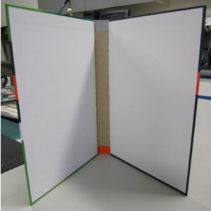
Test strips were taken across the book after removal of the pages, as described earlier. The photographs below illustrate the process.
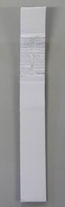
Photographs showing the inside and outside of a test piece. The zone where the pages have been removed from the inside of the spine is clearly visible.
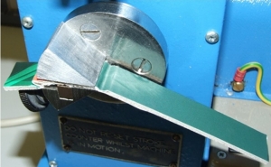
The test piece is inserted in the modified lower clamp with 75mm extending on the longer side and with the cover fold line just protruding.
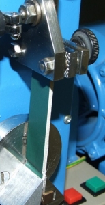
Left: the assembly is rotated into the vertical position and the upper clamp applied.
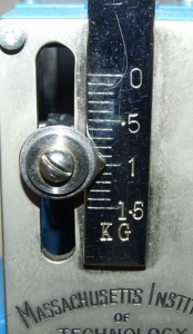 Left: A load of 1kg is applied to the sample.
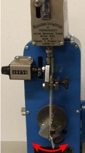
This photograph shows the test piece in the neutral position (unfolded). Once set in motion, the lower clamp oscillates through an angle of 135° ±2°, both to the right and to the left of the position of the unfolded test piece.
This action folds the test piece along the line where the book cover is normally opened and closed.
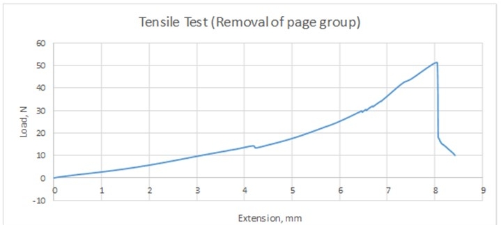
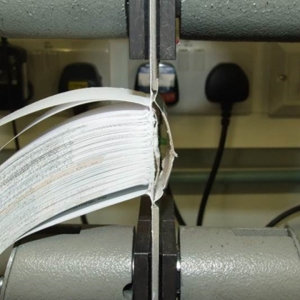
Tensile strength (‘inner page groups’)
This property was measured based on BS EN ISO 527-3 (BS 2782-3 Method 326C) with an Instron 5565 Tensile Tester equipped with a 100N load cell which confirms to ISO 7500 class 0.5.
25mm strips cut with a guillotine across the book specimens were trimmed to approximately 150mm long and a “group” of pages from the middle of the book was selected and clamped in the lower jaws. Care was taken to ensure all the pages, and only pages from that group, were held. The two portions of outer cover were clamped in the upper jaws.
The gauge length was set to 50mm in each case and the extension rate was 10mm/min. The jaw types used were pneumatic with rubber faces of size 25mm x 50mm.
A load-extension curve was generated (see over for an example) and the ultimate force required to detach the group of pages was recorded.
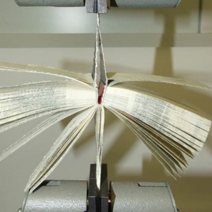
The photographs below demonstrate the process.
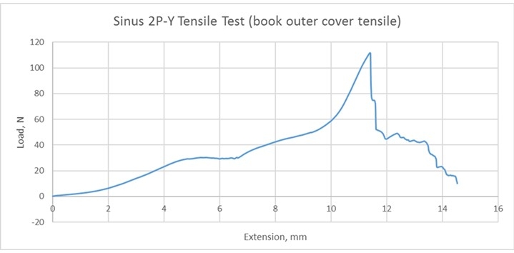
Tensile strength (‘outer covers’)
This property was measured based on BS EN ISO 527-3 (BS 2782-3 Method 326C) with an Instron 5565 Tensile Tester equipped with a 100N load cell which confirms to ISO 7500 class 0.5.
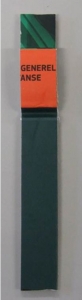
25mm strips cut with a guillotine across the book specimens were trimmed to approximately 150mm long. One outer cover was clamped in the upper jaws and the other clamped in the lower jaws.
The gauge length was set to 50mm in each case and the extension rate was 10mm/min. The jaw types used were pneumatic with rubber faces of size 25mm x 50mm.
A load-extension curve was generated (see below for an example) and the ultimate force required to break the link between the covers was recorded.
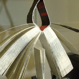
The photographs below demonstrate the process.
Test piece inserted prior to applying load
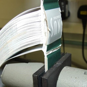
Link between front and back cover sections failed
Discussion
All the tests developed were successful in that they can distinguish the performance of the various book samples/binding types from one another. Over the replicates performed for each sample/test combination, the results were quite consistent which gives confidence in the methods.
Of the four tests, ‘trouser tear’ was least successful because the modes of failure were different for different bookbinding methods. If they had all failed in the same way, then this test could have been used to compare across all the book types. This method could, however, be used to control quality within a particular book-binding type.
The MIT test was the most discriminating with a huge range of results. A greater load could be useful (1kg was used but up to 1.5kg is possible).
Conclusion
- The methods developed were successful in differentiating the performance of the books against various strength/endurance tests that relate to their use. Trouser tear was more limited because the failure modes were different for different book-binding methods. However, it could be used as a quality control test to examine the relative performance of books of the same construction.
- No single construction/material type performed the best in all tests. Therefore, it would be necessary to weight the tests in order of importance.
- It is believed that these tests could form the basis for the development of standards for use across the industry.